Germanium. It sounds exotic. It’s an inferior material for an electronic part but something makes it desirable some 50 years after its original use in guitar effects.
So of course, I had to build a fuzz based on this element. These are not good starter projects for a few reasons, one being the polarity is opposite from other projects (it uses negative 9V power) and another is that germanium transistors are notoriously finicky, you have to get jusssst the right ones, and set them up in jusssst the right circuit. So I got a few other projects under my belt first.

First thing I did was order a PCB through MadBeanPedals.com – of course by the time I decided to do this the project & board had been discontinued. One of the forum regulars was kind enough to send me one he had etched for his own use. It looked awesome. I already had a “RoadRage” board from the same site, so I knew I could provide the -9V easily enough.
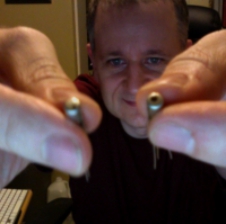
Next was getting those finicky transistors! I ordered the cheapest set I could from SmallBear. This is highly recommended for anyone building this project! Steve at SmallBear tests each set, finds the ideal resistor matchups that give just the right sound and electrical response (based on the official Dunlop/Arbiter Fuzz Face) and supplies both the transistors and the resistors in clearly marked baggies. It’s definitely a deal, even though it seems rather expensive for a couple of little parts.
The next part of the project always comes all at once. Building! I usually start by saying “Well, why don’t I just solder on the sockets” and then say “While I’m here, I’ll put the caps on. Easy enough” and that ends up with “resistors are easy too…” and before you know it the thing is assembled. Mind you, with this one some of the holes were too tiny for the 22 AWG wire I like to use, as well as some of the thicker leads on some of the caps. I ended up using the point on my X-Acto knife to ream them out bigger. That took longer than I’d like.
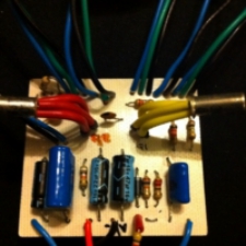
The next part that also usually takes longer than I’d like is the pots, switches and jacks. Cut, strip, tin and solder way too many wires to get it to a point where I can test it. It’s a healthy afternoon’s work, anyway. I tested it first with some PNP 2n5087 silicon transistors which I already had – I figured I would know if it worked and risk a few cents rather than a few dollars. They were way way too quiet (and didn’t fuzz at all) but at least I knew it worked! I plugged in my precious germaniums after giving them some socks to keep warm and safe, and it became loud and raunchy! In this case that’s a good thing.
At this point I have a working pedal though it’s hardly a pedal. Can’t stomp on it, you see. I have an enclosure set aside for it, but I need to figure out how to drill it and what color to make it (I have gold paint but that may be a bit too flashy).
As for the controls, I could have 6 knobs (input attenuation, power sag, transistor bias, fuzz, output volume, and boost level) and two switches (boost only or boost + mids and a “fat” switch). I clearly can’t fit all of those on the size enclosure I have in mind. I will likely leave out the power sag, since I don’t really like that sound.
In the meantime, I have set up two or three dummy layouts using cardboard. At first I was convinced that I would have to lay out the board in landscape orientation, that way the pots would line up all along the top, ZVex style. That leads to too many compromises and there is less room inside for other components like jacks and switches. it looks like I will have to put the switches at the top face of the box, like “eyebrows” above the knobs, and will probably fit just around the DC jack.
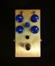 Well, I did the drilling. Â I started with the DC jack, fit the two switches around it, and worked my way downwards, but I didn’t quite get the centers exactly right, for some reason… Â I tried to measure very carefully, but the rounded edges and the fact that the bottom is wider than the top make it really hard to measure. I may be able to make it not as obvious with the painting, and putting the center knob’s label above instead of below. Â In any case, it’s good. Â Now, what color?
I have to debug the grounds on this unit and my silicon fuzz. I can’t seem to have them both plugged in to the same daisy chain, though I have a bunch of other negative ground ones on the same chain that don’t cause the same problem. Â At the moment I have it working with a separate DC power supply, and sometimes it works off the same daisy chain, but it’s a bit flakey.
This sounds much more overdrivey and aggressive. Â The silicon one has more of a buzz. I can get extremely similar sounds out of both, but this one can get… “looser” – more grainy, perhaps and I suspect it gets more gain, though the silicon one definitely has more volume. The input trim control was definitely worth putting in, it really helps balance the guitar volume to have a smoother taper instead of the “cliff” I was finding earlier. Â It’s also fun to dial it up, the fuzz way down and crank the boost. Â Very tasty dirty boost.
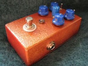
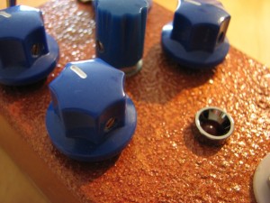
I finally painted it.  I wanted a coppery colour, but all I had on hand was a gold and a red spray paint.  I thought I was so clever in that I could paint the gold base and just dust a bit of red on top.  They were different types of paint, which may have added to the difficulty!  The gold made this cool pebbled finish and the red caught in the grooves to make it look coppery, but this took me about two days to get just right!  Sadly, I don’t think it’s all that durable either, so I took pics quickly so that I could see it at its best. I don’t think I’ll ever do that again, I can probably get a copper textured paint for $7 or $8.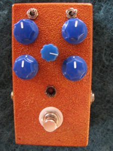
Leave a Reply
You must be logged in to post a comment.