M-Audio StudioPro 3 repair

First of all, let me say “hi there, Googlers!”

I owned the M-Audio StudioPro 3 speakers for quite a few years before they started to fail on me.  They were not too bad, gave decent sound at reasonable desktop volume.  In the last year or so, the right speaker conked out.  Well, it played, but was really really quiet.  I replaced the cable a few times, and tested with an oscilloscope that yes, it was actually receiving signal, but very weak.

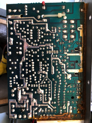
I opened it up and couldn’t see any immediate issues, like loose connections or popped capacitors.  I tried making a better solder joint on the wire leading to the right speaker jack, but didn’t notice an improvement.

I would probably have been wise to obey this

Much of my research leads to the understanding that these units will eventually fail, even if I fixed it now.  I decided I might as well convert the speaker into a passive speaker, and bypass the amp entirely.  I first thought this was as easy as attaching the speaker terminals, then I realized I still need the crossover, of course.  I just needed to find it on the board.

With the help of this page (thank you Yashar), I found at the very bottom of the page a rough estimation of what the crossover will look like in this speaker.  It is slightly different from the AV40, but the general layout of the two inductors helped me locate the general area I was looking for.

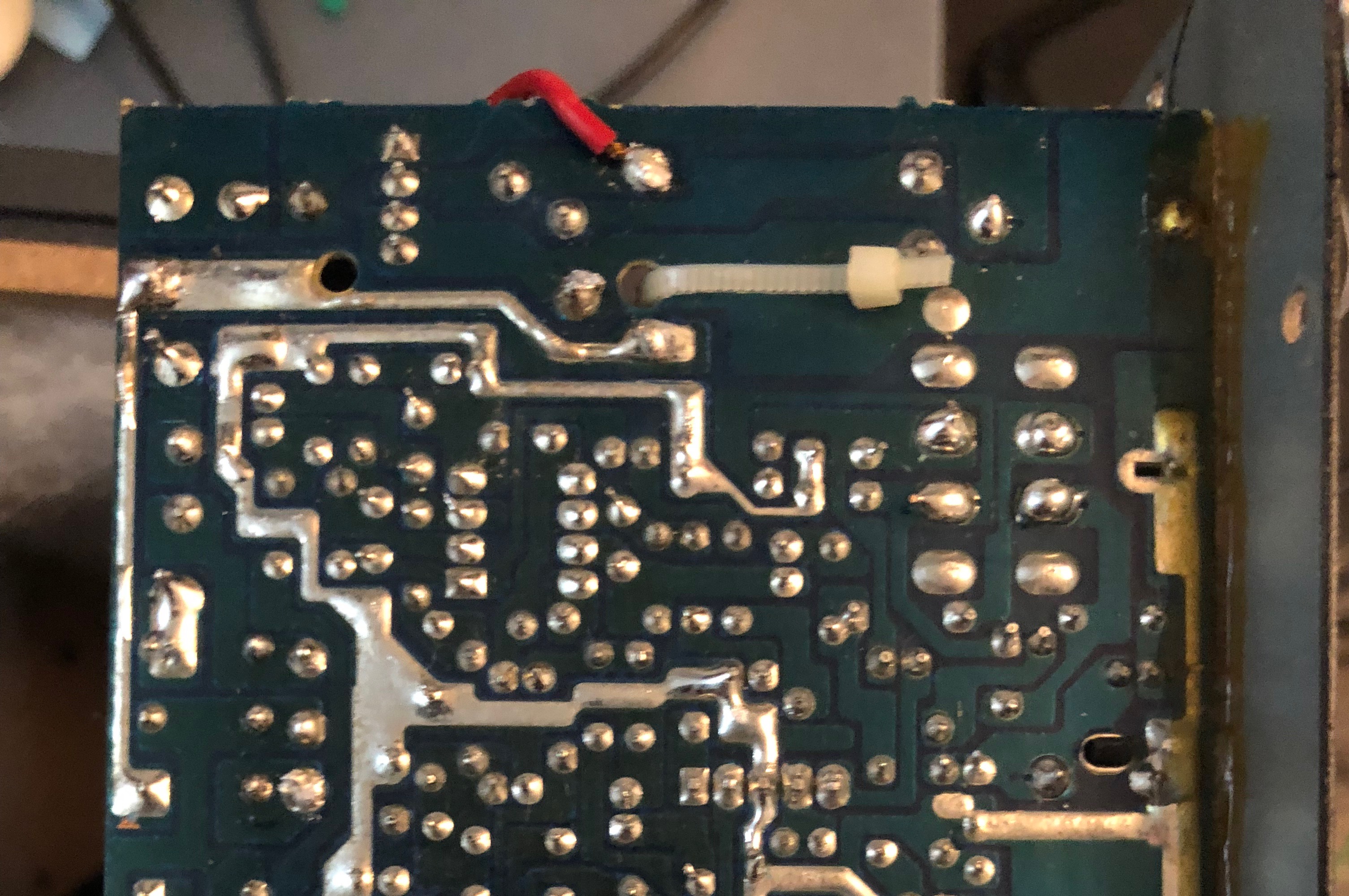
Armed with that and a little function generator I was able to find the spot after the power amp and before the crossover.  Here it is, with the original output wire removed from its spot and soldered on to an existing joint.

I removed it shortly after and threaded the wire through the hole alongside the zip tie for a small amount of strain relief.  Now the 1/8″ jack, instead of sending amplified signal OUT to the right speaker, is an input for amplified signal.  In other words, it is now a passive speaker, just like the right side one.

I can leave it unplugged from AC and still use it, as long as I have a small amp, like the little LEPY amps on Amazon/AliExpress.  The speakers seem to be rated 10W and 4ohms so I certainly can’t drive them hard with that little amp, but I think I can easily get a lot more life out of them, especially with the right one being significantly less dead than before.

I can’t guarantee that I did this right, and maybe someone will correct me, but I think I found a simple solution to save these.

Here’s the full bottom side of the PCB

Posted

in

,

by

Tags:

Comments

15 responses to “M-Audio StudioPro 3 repair”

  1. Aaron Sanchez

    Could you post a picture of the entire pcb bottom view?

  2. Jonathan

    Posted, though I had to scale it down a bit.

  3. RD

    HI,
    Do I only have to re-solder the red wire?
    Thanks

    1. Jonathan

      Yup, if I remember correctly, that was the only change I needed to do. Let me know how it goes.

  4. Ross

    Thanks! Still planning to do after getting a receiver.
    The signal will comes from PC into a new Amp and then goes to the same input posts?

    1. Jonathan

      Yup, that’s the idea.  Basically the one speaker had the amp in it, so nothing changes in the other (passive) speaker, just the modified one will have some dead electronics in it.  Leave that one unplugged from AC of course.

      Verify the impedance and wattage before using them together.  I hope it works for you, no guarantees of course.

      1. Justin Adair

        I wish you had posted a picture of the top to view the capacitors and stuff as I am experiencing the same issues.

        1. Jonathan

          I’m not sure that would mean anything… since the intention of the mod here was to bypass all of that.

  5. Zacky

    hello, how did you open it?

    1. Jonathan

      There’s a whole bunch of small Philips screws on the back.  Should be easy enough.

  6. Frank

    Hello Jonathan.  I had my set of StudioPro 3’s since 2006.  My local radio repair shop now solely focuses on car audio.  My monitors have developed a feedback sorta hum when they are played at any sort of appropriate sound levels.  I swapped out the original cables for more beefy cables incase it was outside electrical interference.  Changed ac outlets, even ran an extension cord from a outlet on a different circuit breaker from my pc. Nothing I have done took away the hum.  Any tips of what it might be and what to look for? I really want to keep and use them. They have sentimental value.  Thankyou any input is welcome. 😊

    1. Jonathan

      That may be beyond my skill level, but let’s see… same volume hum no batter how loud the amp is turned up?  Could be a physical vibration, check if everything is tightened down.  Otherwise I would guess it’s the power section, maybe the transformer?  If you do look at this, please be very careful when playing with power sections.

  7. Manuel

    that model 80to 90% of the electrolytes caps go bad some of them complely open replace all of the electrolytes capacitors and you should be ok

    1. Ross

      Hi, visually caps looks just fine.
      The board is very tough to handle, everything is tight there.
      However, I like the sound reproduction of these speakers. Tried soem replacements, and they were not so clean and tight.
      Do oyu have a list of the capacitors? I could try to replace them one in the time.
      Thank!

  8. Mario

    Can you please post a picture of the other side of the PCB Board

Leave a Reply to Zacky Cancel reply